How to use the PIC16F1823-I/SL with a BASIC Stamp

With more than 60 million transistor ICs shipped each year, the PIC16F1823-I/SL is a popular choice for embedded projects. However, if you don’t know how to use it with a BASIC Stamp or other development tools, you’re at a loss. In this blog post, we’ll show you how to use the PIC16F1823-I/SL with a BASIC Stamp and some of the best programming techniques for this microcontroller. We’ll also discuss some of the available libraries and tools that can help make your embedded project go faster.
What is the PIC16F1823-I/SL?
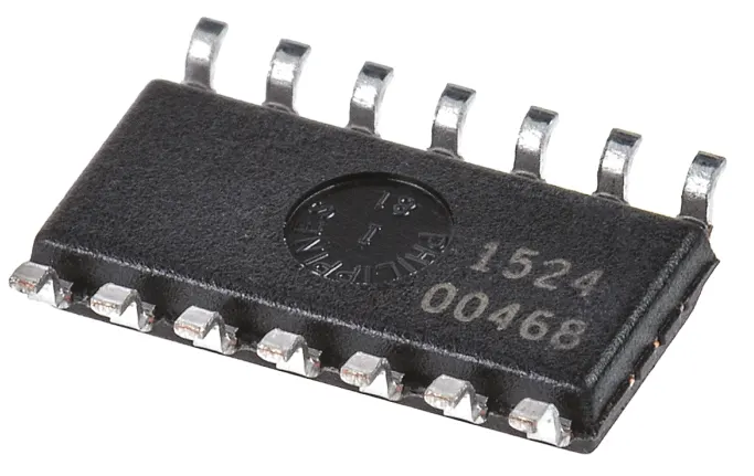
The PIC16F1823-I/SL is a low-cost microcontroller from Microchip Technology Inc. It features 18 GPIO pins and 2 USB ports. This microcontroller can be used with the BASIC Stamp development board to create simple applications.
To use the PICF-I/SL with the BASIC Stamp, first connect the board to your computer using the USB connector. Then install the BASIC Stamp software on your computer. Once installed, open it and click on the “File” menu item. Select “New Project” and enter “PIC16F1823_I_SL” as the project name. Next, select “Microcontroller” from the “Type” dropdown list and click on the “Next” button. On the “Microcontroller Properties” window, set the clock speed to “8 MHz” and the data width to “16 bits”. Finally, set the number of program storage locations to “8” and click on the “Finish” button.to 8 MHz and choose either I2C or SPI as the communication port. Finally, set the programming mode to BasicStamp (or any other compatible mode) and click on the “Finish” button.
Now that we have created our project, we need to create a code file for this microcontroller. To do this, open up a text editor such as Notepad or Microsoft Word and enter the following code:
This code will start up our microcontroller and allow us to access its 18 GPIO pins. We can also use these pins to control various aspects of our sketch using standard programming techniques such as conditional statements and loops.
Connecting to the PIC16F1823-I/SL using a BASIC Stamp
The PIC16F1823-I/SL microcontroller is a great choice for beginner programmers because it has simple commands and capabilities. This microcontroller can be connected to the BASIC Stamp using a serial port, which makes programming easy. The BASIC Stamp can also be used to control the PIC16F1823-I/SL and read data from sensors. In this article, we will show you how to connect the PIC16F1823-I/SL to the BASIC Stamp and use it to control a LED.
Programming the PIC16F1823-I/SL using BASIC Stamp
The PIC16F1823-I/SL is an 8-bit MOS microcontroller with a SAM3X12E slave oscillator. It has 16 kB of flash memory, 2 kB of RAM, and an I/O port. The PIC16F1823-I/SL can be programmed in BASIC Stamp using the Microchip Software Library (MSL). This tutorial will show you how to use MSL to program the PIC16F1823-I/SL.
First, make sure you have the MSL installed on your computer. You can download it from the Microchip website. If you don’t have MSL already installed, you’ll need to install it before proceeding with this tutorial.
Once MSL is installed, open it up by clicking on its icon on your desktop or in your Start menu. Then click on the “File” menu and select “Open.” Navigate to the folder where you downloaded the PIC16F1823-I/SL firmware image file (if you downloaded one). Double-click on the file to start up MSL.
Once MSL is open, click on the “Tools” tab and select “Programmer.” In the programmer window, select “PIC 16F 18xx Series MCU CPU,” and then choose “PIC16F 18xx Series Slave Oscillator.” In the Programmer window’s Arguments text box, type in
Testing the Programmed Circuit on an Arduino Board
If you have an Arduino board, you can test your programmed circuit using the serial monitor. Open the serial monitor, and connect your Arduino to your computer via a USB cable. Type in the following commands:
AT+GMR
AT+CMGF=1,2
This will configure your Arduino to use UART mode (you can also use AT commands if you’re not using a USB cable). If everything is working correctly, you’ll see the following output in the serial monitor:
The first line shows that the Arduino has detected an incoming call (GMR). The second line tells us that we’re currently connected to UART 1 at 115200 bps. Each line after that shows what was sent/received on that UART channel. The last message in this sequence says “end of file.”
How to use the PIC16F1823-I/SL with a BASIC Stamp
The PIC16F1823-I/SL is a 16-bit microcontroller that has a wide range of features and capabilities. It can be used with a BASIC Stamp development board to create quick, easy projects. This article will show you how to use the PIC16F1823-I/SL with a BASIC Stamp.
First, connect the PIC16F1823-I/SL to your computer using the provided USB cable. Next, download the BASIC Stamp development board software from the website and install it on your computer. The software will help you configure the PIC16F1823-I/SL for use with your project.
Next, open the BASIC Stamp development board software and click on “Configure.” In the “Configuration” window, select “PIC16F1823-I/SL” from the list of devices. Select “Onboard Peripherals” from the “Device Type” dropdown menu and select “Serial.” Click on “Next.” In the “Serial Port Settings” window, enter “/dev/ttyAMA0” in both of the fields labeled “COM Port Name” and “File Mode.” Click on “Next.” In the “Programming Options” window, set the following options: Device Name: PIC16F1823 – I / SL
Load Address: 0x00001000
Baud Rate: 9600
Click on OK to
What are the advantages of using a PIC16F1823-I/SL with a BASIC Stamp?
The PIC16F1823-I/SL microcontroller is a powerful and affordable chip that can be used in a variety of projects. One of the great features of this chip is its compatibility with the BASIC Stamp programming language. This article will describe how to use a PICF-I/SL with a BASIC Stamp, and provide some examples of how this combination can be used in different projects.
One of the great things about the PICF-I/SL is that it has several built-in features that make it easy to program. For example, the chip includes an LED driver that lets you control LEDs on your project easily. Additionally, the PICF-I/SL supports EEPROM memory, which makes it perfect for storing data or program instructions.
When using a PICF-I/SL with a BASIC Stamp, you can create simple programs that control basic functions on your project. For example, you could use a BASIC Stamp program to write data to an EEPROM on your project or to control an LED using commands sent from your computer.
Overall, using a PICF-I/SL with a BASIC Stamp provides many advantages over traditional programming methods. These include ease of use and compatibility with common hardware and software tools.
Conclusion
In this article, we will show you how to use the PIC16F1823-I/SL with a BASIC Stamp. We will start by explaining the different pins that are available on the board and what they do. Next, we will demonstrate how to use each pin in order to configure the microcontroller. Finally, we will provide some tips on using the microcontroller with a BASIC Stamp.


